Hack of the Whenever I Get Around to It

September 23, 2009

GSquelch – command-line silence filter

Filed under: Uncategorized — Chris Merck @ 9:50 am

I like to read. Quite often however I come across an unfamiliar word, especially while reading in a foreign language. If I am at a desk I will underline the word(s) and come back later with a dictionary to learn the meaning. However, if I’m trying to relax, lying down with a paperback, it is inconvinient to underline or write down words. I would prefer verbal note-taking, but if I just run a recorder, mainly silence is captured. I want the voice-activated recording feature of those 90s personal voice recorders on my PC. But it does not seem like a straight-forward, costless, and free solution is available. Moreover there is some demand, as seen by the five posts and partial solutions on LinuxQuestions.

So, I wrote GSquelch, which allows for the filtering-out of those silent sections automatically at run-time. A ring-buffer is employed to ensure that the dictations are not cut-off and that a lead-in and lead-out are provided to capture soft sounds which often are found at the beginning or end of phrases but are not loud enough to trigger a traditional squelch.

Currently only unsigned 8-bit mono is supported, but I will soon add support for other common formats.

Here is the C++ source code:
(more…)

August 19, 2009

The Uncountably Many Body Problem

Filed under: Uncategorized — Chris Merck @ 3:53 am

Here is a problem that has been on my mind for some time. I have made some progress, but there is yet much to be done!

Suppose there is a system of uncountably many particles under Newtonian gravitation. Assume these particles may pass through one another; i.e., that they never collide. This is essentially an extension of the N-body problem; however, the presence of uncountably many bodies makes possible a phase-space density formulation. Let ⍴ be a density function over a 6-dimensional phase-space (consisting of 3 position and 3 velocity dimensions). Using Newton’s law of gravitation the acceleration at any position is found to be

Acceleration Integration

Acceleration Integration

Then the change in the phase-space density at any position x and velocity y may be derived:

UMBP Equation of Motion

UMBP Differential Equation

where the gradients are three-dimensional and taken with respect to the position or velocity components as indicated.

I am curious about stationary states of this equation. A stationary state is a particular phase-space density which undergoes no change under the influence of gravitation. So far I have found:

  1. all mass focused at a point with null velocity
  2. a uniform distribution of matter throughout all space with the same arbitrary velocity distribution at each point
  3. a uniform ring of matter orbiting the center of gravity at the orbital speed
  4. the superposition of two such rings but with opposite orbital directions
  5. a uniform spherical shell of matter with orbiting the center of gravity at the orbital speed with velocities uniformly distributed in all tangential directions

Furthermore, I suspect that solutions along the following lines may be found:

  1. spherical shells of different sizes may be superposed but with decreased speed for inner shells and increased speed for outer shells to account for change in the net force of gravity
  2. a gaussian distribution of matter about a center with velocities pointing exactly inwards and outwards with some gaussian-like dependence of speed on distance from center
  3. a gaussian distribution of matter with velocities distributed gaussian-like among all directions and speeds

The questions I would like to answer include

  1. Can all stationary states of a certain dimention be simply charicterized?
  2. Which stationary states are stable? I.e., which deviate slightly when slightly perturbed?
  3. What is the Lagrangian formulation of the UMBP?
  4. The quantum mechanical version?

January 26, 2009

Memory Restricted Brainfsck

Filed under: Uncategorized — Chris Merck @ 4:08 am

This past summer I had a rather crazy summer research semester. I kicked it off with a trip to Norway to take a course on Engineering Entrepreneurship and generally just see the beautiful country. By the time I returned to Hoboken my copy of Svozil’s Randomness and Undecidability in Physics had arrived via interlibrary loan. I got the book just to read his analysis of the logistic map, but then I fell in love with the whole thing. Reading this book opened my mind to some way-abstract modes of thought, for better or for worse. I will never think about physics and comp-sci the same way.

Although my summer research proposal was to build a digital attractive-maglev controller, and I actually spent most of my time setting up an ultimately flawed raman gain spectroscopy experiment, my most productive time was during the last week of the summer in which time I wrote A Paper on Memory-Restricted Brainfucks.

The basic idea is to see what happens when we take a simple machine model, like brainfuck, and restrict the memory to just a few cells which may take on only a few values. The result is a so-called “finite machine” which is, of course, not Turing-complete, but which may be provably complete in some analogous sense. The paper contains an exposition of the finite brainfuck (called Q), an outline of a finite-completeness proof, and results of some brute-force attempts to find the elegant and neat implementations for all functions of a particular order.

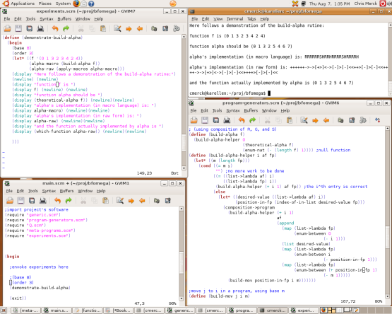
dev-screenshot

developing in mind/GVim/Scheme/Ubuntu/GNU/Linux/X86/Nature

All the source code implementing the Q interpreter and the experiments thereupon is written in Scheme and is included at the end of the paper.

November 21, 2008

Simulation and Analysis of Maglev

Filed under: Uncategorized — Chris Merck @ 7:16 pm
Tags:

One of the project objectives for SKIL is to create a simulation of the experiment being run. We were supposed to use LabVIEW, but LabVIEW gives me indigestion, so I used MIT/GNU Scheme instead. The simulation is supposed to model the feedback loop which is formed by the levitation apparatus and the electronics controlling it. Essentially the simulation takes as input a “control function” and outputs the expected behavior of the levitation.

So I threw together some scheme code to simulate the motion of a magnetic object in a changing magnetic field, which is determined by the current of the simulated electromagnet, which is in turn controlled by the changing voltage applied. That applied voltage is the output from the “control function”. The input to the control function is the elevation of the object.

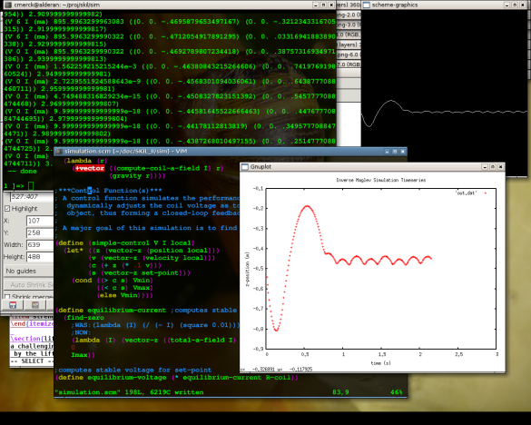
Below is shown the first screenshot I have of simulation output. On the left is the numerical output of the various parameters (unlabeled) and on the right is the elevation vs. time plot of the object. The control function that was used was quite naive: it set the voltage to minimum or maximum when the object was “too high” or “too low” respectively. You can see that the naive control function does not stabilize vibrations properly, so the oscillations get out of control:

showing the effect of a poor control function

showing the effect of a poor control function

I eventually added gnuplot output for fancier graphs and devised a better control function. A screenshot of a testing this better control function is shown here:

effective-control-function

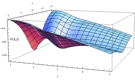
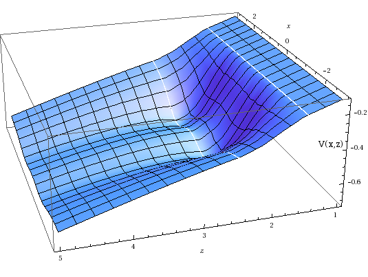
The simulation depicted above only handles one dimension of motion, but there are 3 in the real levitator. So, I put together a theoretical model of the levitator in 2 dimensions (the third dimension is symmetrical and so it is not shown). The result was the following “potential curves”. These curves are analogous to terrain that an object is rolling over. The object will tend to move along the valleys and settle in the pits (lower energy regions).

a potential energy curve which takes into account gravity, permanent magnetism, and the stablizing effect of the control function

a potential energy curve which takes into account gravity, preeminent magnetism, and the stabilizing effect of the control function

a potential energy curve for two electromangets spaced a few inches apart, in which one can see two "potential wells"

a potential energy curve for two electromangets spaced a few inches apart, in which one can see two

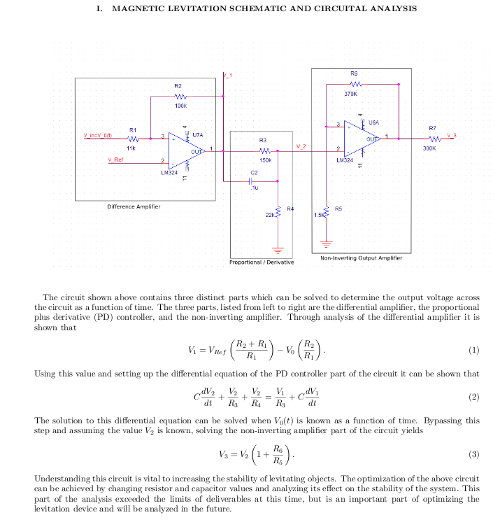
Lastly, Kevin put together an analysis of Barry’s “anti-gravity relay” circuit:

Kevin's Analysis

More details of the simulation and analysis can be found in the project writeup.

November 16, 2008

Multi-Dimentional Attractive Magnetic Levitation – The Conception

Filed under: Uncategorized — Chris Merck @ 9:24 am

Each semester at Stevens we physics majors are required to work on a so-called “SKIL” project. For this project there is no assigned project, instead we students select a project we feel is both educational and possible to make some headway on during the course of a semester. Last semester on the first day of class we all sat down and discussed our project ideas – everyone was to present one or more ideas, and we were going to argue the relative merits of them and select 3 or 4 viable ideas and choose teams to work on them. I entered the room that morning with a few ideas in my head, amoung them a low-cost usb-powered EEG, improvements to the RepRap project, and something else I have since forgotten. But, during the class I remembered a cool project I had seen on the internet a while back which involved using an actively regulated electromagnet to suspend small metal objects in mid-air. The project had the aesthetic appeal of a good SKIL project, but it lacked the nessisary complexity and origionality. So, I doodled a little imaginative doodle involving a horizontal array of coils suspending and moving the metalic object beneith them, with the ability to control not only the vertical but also the horizontal position of that object. The idea was a hit, and we formed a team of 6. Six may sound like a small number, but this was half of the physics majors in my graduating class, all working on one project. The team size was unpresidented and presented a real organizational challenge. Nevertheless we stuck with the project and now, looking back, I am quite pleased that we did.

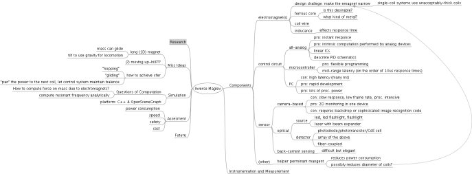
The first step was to do some brainstorming. I apt-got myself a copy of FreeMind and made the following mind-map (click for enlargement):

inverse-maglev1

After the brainstorming we starting attacking the project from many angles at the same time. This worked for several reasons: 1) the project split into fairly independant sub-projects, 2) we had 6 people, 3) we talked as a group breifly before each lab and decided on a plan of action for that week and a tentative plan for the following week, but after 20min or so we split into at least 2 independant sub-teams and most importantly in my opinion 4) what we learned in persuing one end was applicable towards another – since we were designing and constructing simultaneously, we were able to figure out what was and wasn’t going to work in reality even while drawing up a plan. In the end we spent approximately 500 man hours on the project (6 people * 4-hour weekly lab * 15 weeks + some people became sort of obsessed and moonlighted many a long night = ~500 hrs).

Here’s a photograph of the device in action:

Levitating a Screw Driver

Levitating a Screw Driver

November 15, 2008

Polarizing Optoacustic Mixer

Filed under: Uncategorized — Chris Merck @ 2:12 am

Goal:

To mix two audio signals using amplitude modulated lasers as the transition medium and a polarizing filter for the selection of the mixing ratio.

Concept:

Two low-cost red laser pointers which normally use 3VDC power supplies are modified with an audio transformer so that for each laser the supply voltage varies about 3VDC proportionally to an audio signal. The fluctuating supply voltages result in fluctuating beam brightnesses. The beams are made colinear with a 50/50 beamsplitter and the lasers are rotated along their beam axes such that the polarization of the light due to either laser in the collinear beam is orthogonalized. The beam then passes through a hand-held polarizing filter which selects out a linear combination of the orthagonal polarizations and so also a linear combination of the audio signals those polarizations encode. The beam post-polarizer is then incident on a (passive) phototranstor attached to a high-gain (741-based) pre-amp and a boom-box, so that the mixed audio signal may be heard in real-time.

Photos:

an annotated beam’s-eye view
(note Steve’s Cell-Detecting Helical Antenna of Death in back left)

Steve hand-mixing some beats

a top-view of the transmitter in the dark


a beam’s-eye view in the dark
(You have to imagine the otherworldly blend of Moondog and eurotrance emanating from the boom-box.)

the development and testing team
(Raj, Langley, Merck, Englehardt, Steve)

Video Demonstration:

DJ Raj demos the POM

Schematics:

Each of the transmitting lasers requires a modulation circuit like the following. Note that you could use many other methods to modulate the laser, but I have found the transformer to be very effective for audio:

the wiring diagram for a single-laser transmitter

the wiring diagram for a single-laser transmitter (click to make bigger)

October 24, 2008

Rithmomachia

Filed under: Uncategorized — Chris Merck @ 7:51 pm

A few years ago, after reading about it in Pappas’ Magic of Mathematics, I built a board and pieces for an ancient game similar to Chess, called Rithmomachia, the Philosopher’s Game, or Zahlenkampfspiel. Recently I brought the board out of mothballs. Here are some photos from todays game:

the white pyramid approaches
(Kevin left, me right)

much to be gained, much to be lost

white is victorious

we both have a bit of a headache now

For a quick guide I wrote up this document. It is useful while playing with new players.

For more info, Googling at random is not terribly effective, due to how obscure the game is, and how much misinformation is out there. Here are some reliable sources imo:

  • The Yahoo! Group for Rithmomachia – There is an active discussion of the game taking place here and Stephen has translated several old texts on the game, which are available for download (thanks!).
  • The Magic of Mathematics – This is where I first came across the game, and from what reference I built my set. You can search inside the book on Amazon.
  • Wikipedia (German)
  • Wikipedia (English) – very little information. Some day I will get around to a major re-write of this article, perhaps based on the well written German version.

—-

At some point I will implement a PC version of the game, probably in C using old-school terminal graphics and i/o, that way it can be run on my ancient 386 laptop!

February 11, 2008

Penny Opto-recognition Software

Filed under: Uncategorized — Chris Merck @ 1:42 am

Penny Opto-recognition Software (POS) is my first excursion into optical image recognition. It is a software program which reads images from any Video4Linux-supported webcam and processes the image to discover the positions of several pennies within the field of view. A geometric representation of the recognized positions is displayed on the screen. Also recognized is a red translucent spoon which is used as a pointer to both digitally and physically manipulate the pennies.

The video is quite self-explanatory:

For the bandwidth-impaired, here are some photos of the system in action:

front view

side view

top view
Source code may be found here: https://guinness.cs.stevens-tech.edu/~cmerck/camera_hacks/
The pennyfix.c file is the one demonstrated here.
The camhacks.c file is an improvement of the peep-hole camera software. More on that in an upcoming post.

January 2, 2008

rtrafmon – Remote Traffic Monitoring without remote software

Filed under: Uncategorized — Chris Merck @ 7:05 am

A New Year’s gift: monitor the upload traffic of any Windows machine remotely, without ever touching the remote machine.

rtrafmon may be downloaded here

Here is screencap of typicall usage (showing VNC traffic to another machine):

Just so it is totally clear what is going on here, let me explain: There are three different machines, A, B, and X. B connects to A over VNC. X then uses rtrafmon with A as its target. X sees the plot above showing the amount of VNC traffic from A to B.

From the README file:

WARNING: this tool is in an alpha stage and so may crash, lag your machine, lag your network, or piss off network administrators. Use it at your own risk.

What is rtrafmon?

rtrafmon is a tool for monitoring a remote host’s network traffic without any software on the remote end. The tool displays packets per second and latency of the remote host on a scrolling plot. The packet rate is a green or red bar graph and the latency is shown with a white line graph superimposed on the packet rate graph.

What is required on the remote side?

The remote host must be reachable on some TCP port (open or closed), and it’s TCP/IP stack must use incremental IPIDs (This is true of Windows systems, but not of most UNIX varieties).
Put simply, an unfirewalled (or partially-unfirewalled) Windows machine.

How does rtrafmon work?

This tool works by sending unsolicited TCP packets to a remote host and gathering information from the responding packets. The packets sent to the remote host have their SYN flag set indicating that we intend to establish a connection on the specified port. If the port is open, the host *must* respond with a SYN-ACK packet. All required information is gathered from the IPID and round-trip-time fields of these SYN-ACK packets. Since the IPID field is incremented once for every outgoing packet, we can tell how many packets were sent by the remote host in between the sending of SYN probes.

Local requirements:

– Linux box with root access
– the hping3 network tool (try “apt-get install hping3” on Debian or Ubuntu)
– SDL development libraries (“apt-get install libSDL-dev“)
– a C compiler (“apt-get install build-essential“)

Building:

To build rtrafmon, just type “make” in this directory.

Using:

rtrafmon works by parsing the output of the hping tool. So a typical usage would be as follows (run as root):

hping3 -i u100000 -S -p 22 216.4.223.98 | ./rtrafmon

This means: send a SYN packet on port 22 to 216.4.223.98 every 100000 microseconds (10 times per second), and send the responces to rtrafmon. The resulting traffic analysis will be displayed in a window.

NOTE: the scroll rate (and thus the resolution of the monitoring) may be changed by decreasing the interval (hping’s -i option). But beware, probing too fast can cause undesirable effects on both the local and remote host. Sending SYN packets too fast can confound some TCP/IP stacks (called SYN-flooding) and results in a Denial of Service.

NAT

Multiple machines behind a single NAT-box (which have their own privite IPs within a LAN) can be monitored (even simultaniously), so long as there is at least one port forwarded through the firewall to each machine. Hping can help you work out the firewall rules (ask Google for more).
December 12, 2007

Hack Keyboard into Magic Wand Clock

Filed under: Uncategorized — Chris Merck @ 4:20 am

I got one of those magic wand clocks as a gift last Christmas, the kind that have a wand made from PCB with eight or so LEDs on it that waves back and forth with the LEDs flashing in such a way that you see text “floating in mid air”, a technique called persistence of vision (POV). It was pretty cool, but I was kind of disappointed when I powered it up only to find that it was mis-calibrated so that the left and right strokes of the wand were out of sync rendering the time unreadable. Solution – bypass the internal LED control circuitry and wire in a keyboard for custom message display!

To do this I used a propeller microcontroller (from Parallax) and a few basic tools. All the required circuitry to interface with the LEDs and control the wand movement was already on the clock’s PCB, I just had to run wires from the propeller to the bases of the LED-controlling transistors and run a line from the wand-detector so that I could sync. After about an hour of playing with Spin code (the unique high-level language for the propeller) I managed to get a stable field of pixels out of the hacked clock:

the pixel-field hovering an inch above the table
the pixel field looking straight at it

a view of the whole set-up, running in the Stevens’ Darkness and Death Laboratory
where Kyle and I worked until the early hours trying to the font to be readable

Then it just took a few more hours to design an 8×4 pixel font on graph paper (done by Kyle), enter the hex into a massive table, and program text scrolling into the propeller chip. Adding keyboard support was a no brainer, since the propeller works – just import the keyboard Spin object! Here is the result:

video of “Hello, World!” on the hacked device

You may download and use my code if you wish, from here (you want the .spin files).

This project was quite entertaining! Now the clock sits in my room and acts as a free-for-all message board for anyone who walks in – they just type on the attached keyboard and their message is added to the scroll!

After using the propeller with this project I would very highly recommend anyone with an interest in microcontrollers (or electronics in general) check it out! It is very powerful, well designed, and most importantly, the hobbiest/hacker community surrounding it is extraordinary!

Other POV links of note:
* U.S. Government hack of a similar clock (uses real-time linux distro)
* Spoke POV (for bicycles)
* MAKE magazine’s POV toy (easy)
* POV analog and digital clocks (lots of photos)
* High Resolution POV (impressive)

Next Page »

Blog at WordPress.com.